Building Your Keyboard
Josh Burgess •
#keyboard#soldering#engineering#how-to#cornes
My Journey in Assembling My Corne Keyboard
What’s a Corne Keyboard?
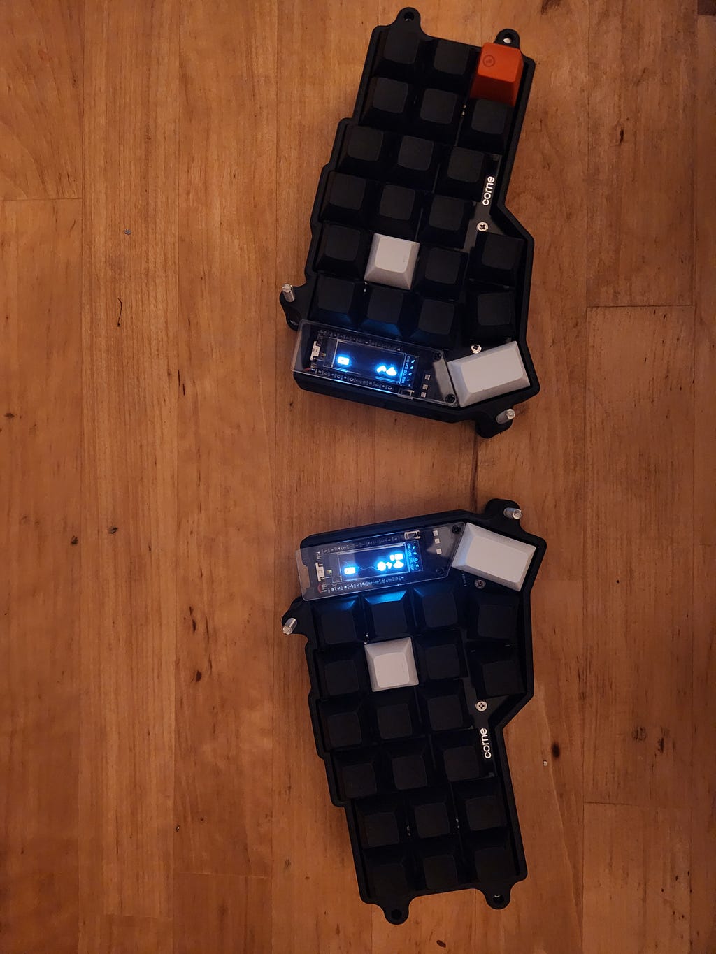
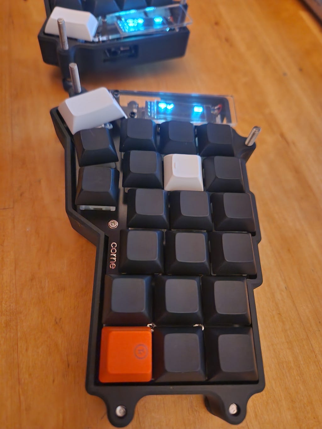
The Corne keyboard is a split keyboard with 3x6 column staggered keys and 3 thumb keys, based on Helix. Crkbd stands for Corne Keyboard. ~ Foostan, GitHub
This keyboard design is open-source and developed by Foostan, a well-known developer in the keyboard community. The design can be modified from the 42-key 6-column layout to a 36-key 5-column layout; however, if you choose this you cannot add the columns back as you need to snap them off of your PCB.
I also needed some soldering refreshers and found a couple of videos about soldering, flux, and desoldering to be helpful.
What you need:
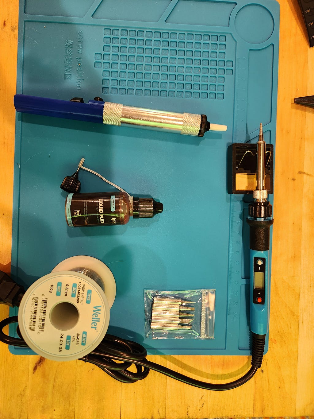
Tools:
- Soldering Iron
- Solder
- Flux
- Isopropyl Alcohol, to clean the flux
- Tweezers, I like the reverse grip
Optional, yet helpful:
- Solder Wick Braid Copper Wire (for undoing your mistakes)
- Solder Pump
- Solder Mat
- Safety Glasses
- Solder Ventilation Fan
- Electrical Tape
- Magnifying Lens
- Multimeter
Net you will need the actual parts to build this keyboard. If you have the means and material, you can 3D print the keycaps and case and even order the PCB based on a design. I went with a combination of places to source my parts, but the main electronics are from Keebmaker. My favorites are Keebmaker, Typeractive, and SplitType
Parts:
- Corne PCBs x2
- Micro-controllers x2
- Controller Pins x48
- Diodes x36–42
- Kailh Switch Hot Swap Sockets x36–42
- TRRS Jacks x2 (optional if you choose nice!nano controllers for Bluetooth connection)
- Reset Buttons x2
- TRRS Cable x1 (optional if you choose nice!nano controllers for Bluetooth connection)
- Key Switches x36–42
- Keycaps x36–42
Suggested Fun parts:
- Keyboard Case x1
- Controller Hot Swap Headers x48
- OLED Screens 2
- OLED Pins x8
- OLED Hot Swap Headers x8
- OLED Covers and Hardware x2
- SK6812 3535 LEDs x12
- SK6812 Mini-E LEDs x36–42
Firmware:
The Wired option of a Corne keyboard can use VIA and QMK, which are a little more user-friendly compared to the wireless option which is ZMK.
The Diodes:
skill: easy
desolder: easy
What’s a Diode?
A diode is a semiconductor that allows the current to flow in one single direction and restricts it coming from the opposite. They also change AC (alternating current) to DC (direct current). A diode can fail due to overheating or an overvoltage spike, which causes a short circuit.
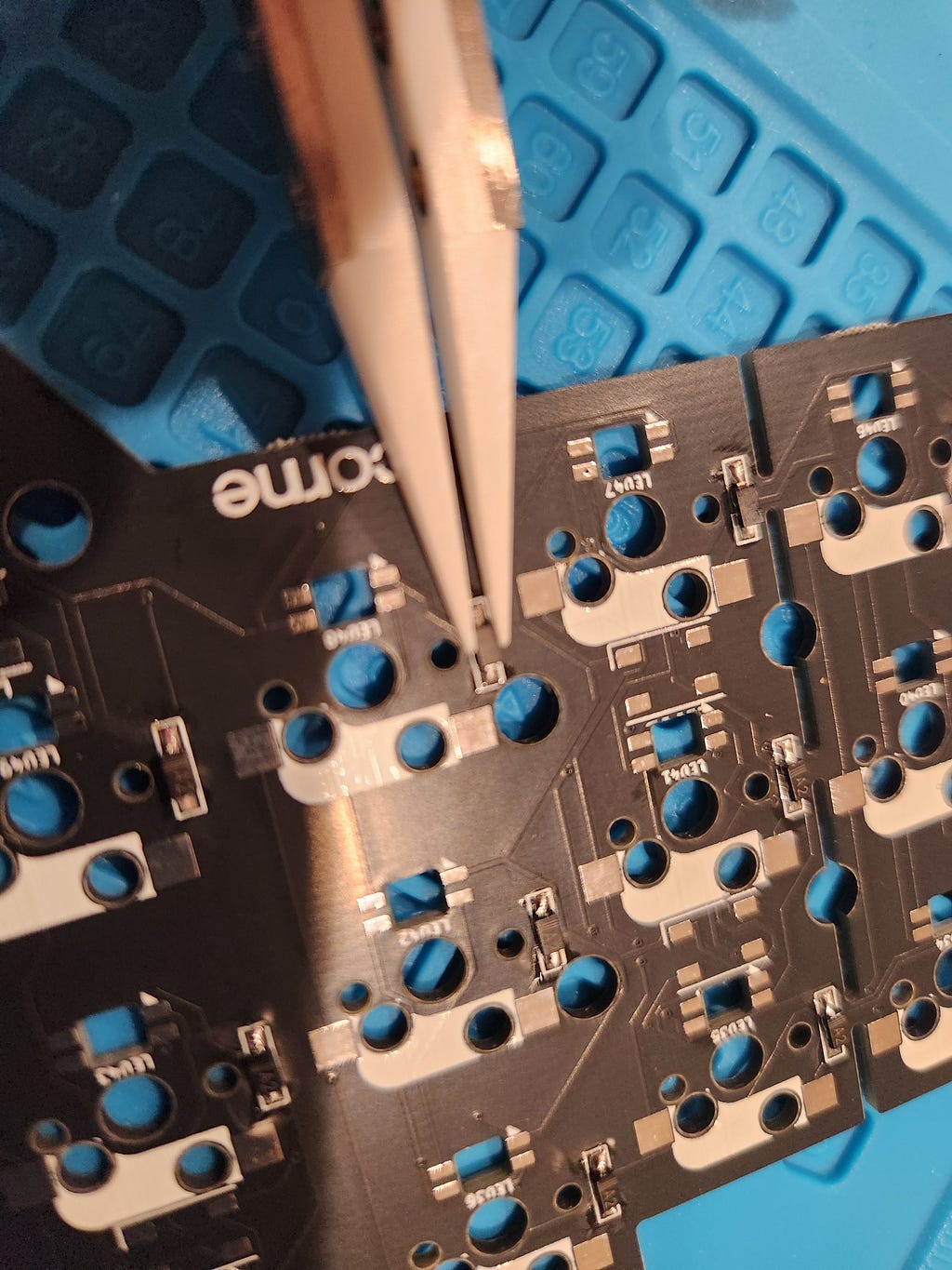
I followed Keebmaker’s Guide to assembling my Corne and set the soldering iron to 400° C. PCB components can burn, so the idea is to be quick. When soldering the diodes, I found it easiest to pre-tin one of the pads in each pair on the PCB. Then take the diode with tweezers and heat the soldered pad, slide and hold the diode and it will harden correctly onto the board. Make sure the 3 lines of the diode are lined up to the line mark on the PCB-designated diode space! Next, go around and solder the other leg to the opposite PCB pad.
Switch Hot Swap Sockets:
skill: easy
desolder: medium

I found pre-tinning all the pads for the switches to be the easiest way to tackle mounting the components. After each pad is tinned, all one has to do is set the switch along the pads and press the iron down on the switch until the solder melts under it and the component will be mounted to said board.
Reset Switches:
skill: easy
desolder: easy
With the reset switch, you have to flip the board right side up (opposite of the diodes) place the legs down through, and then solder the legs to the board on the underside.
TRS Jacks (Optional for Wireless Builds):
skill: easy
desolder: easy
After this step, I had forgotten to take a couple of pictures as these steps went much quicker than earlier ones.
The TRS Jack is very similar to the rest switch, although due to it being a larger component, one may have to apply electrical tape to keep it in place. The TRS jack on the keyboard allows communication between the two boards. This is optional when you build a wireless board because the controllers will then connect over Bluetooth.
Controller Socket Headers and pins:
skill: easy
desolder: hard
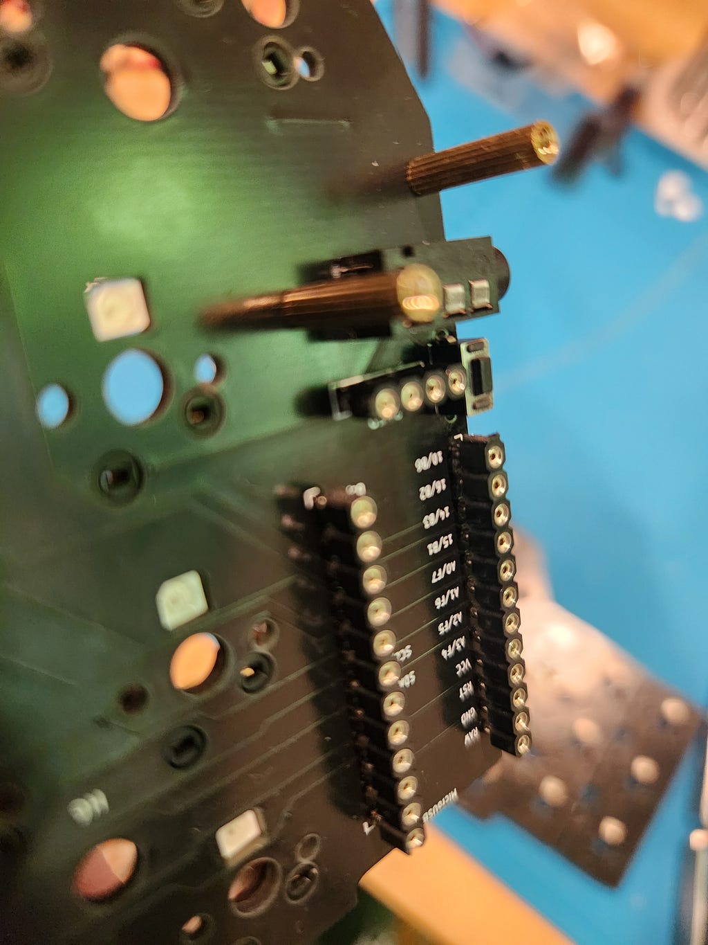
For both headers, it is optional, but highly recommended to use hot swappable socket headers, in case you switch out the microcontroller or OLED screen, and I enjoyed the low profile sockets sold at Keebmaker.
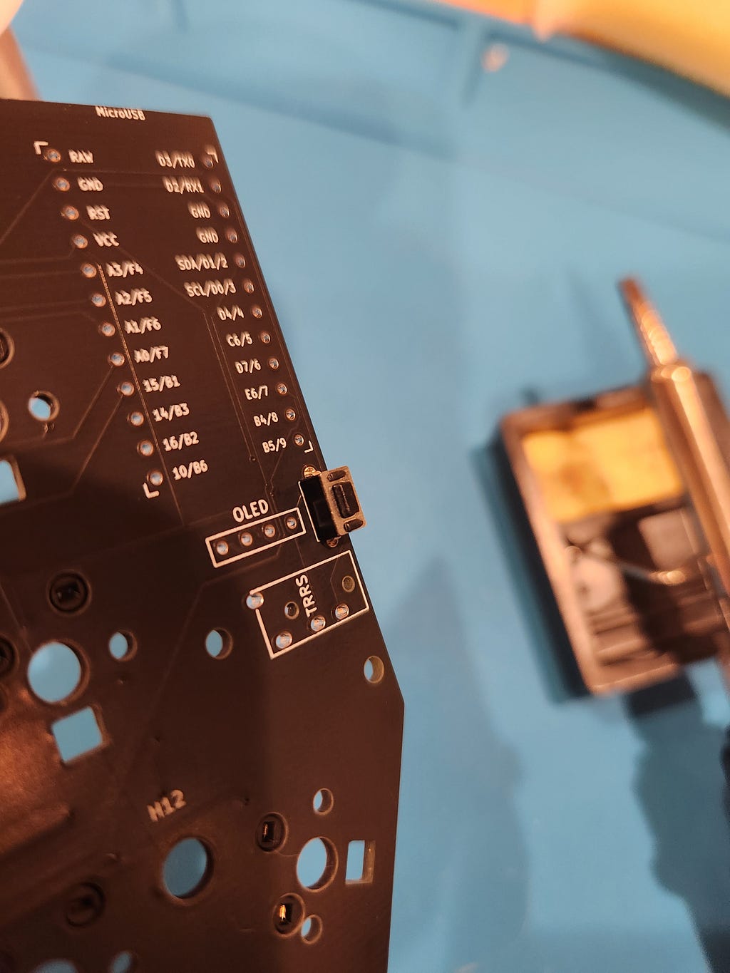
Your controller will have labels next to each hole where your pins should connect to the same label on the PCB where the socket is. I found it easiest to click the pins into the header and then the controller can be soldered. Be sure to quickly solder as this is most likely the most expensive piece of the build with the least heat resistance.
This step is the same for the OLED, just perform the OLED assembly after the battery.
Flashing the Controllers:
This was my favorite part, most of the nuances are explained and well-documented for the wireless builds at https://zmk.dev/. This step requires you to clone the zmk repo and push it to your own GitHub, so you do not create a forked version unless you plan to help contribute to the project. The GitHub actions will compile your preferences as a zip with left and right controller files ready to flash. When you connect your board to the laptop, and double-press the reset switch you, you will see your board mounted and you can drag the appropriate folder to the board connected. It will dismount and you have the keyboard ready to type!
Micro-Controller Battery:
skill: easy
desolder: easy
Some PCB boards will have a place for a power switch, mine did not, and I did not mind the risk of soldering the battery directly to the controller. Strip the wire tips so you can make a direct connection to the terminals at the front of your microcontroller. Black is negative and red positive.
Underglow LEDs :
skill: medium
desolder: medium
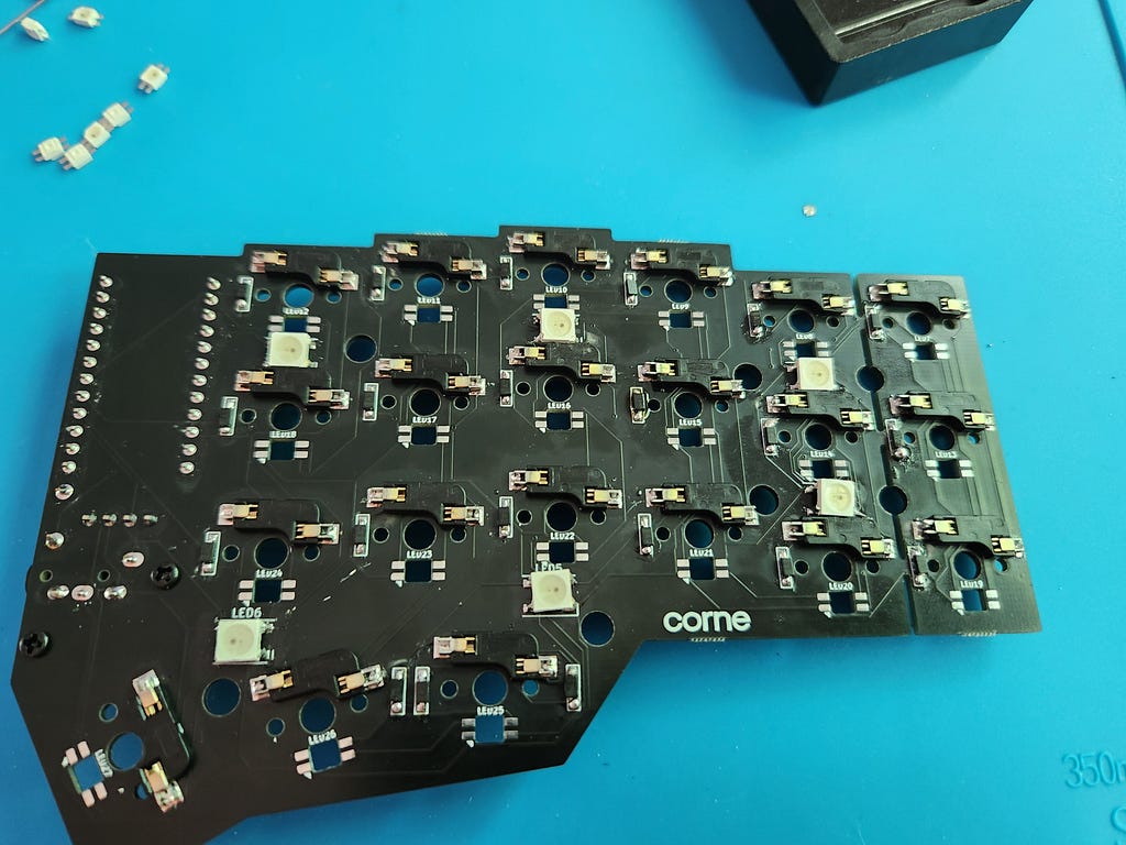
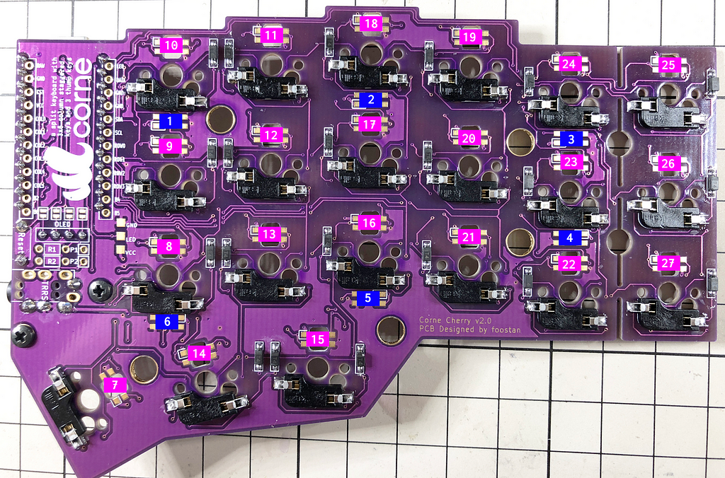
Though I soldered these on, I am not a huge RGB lover. It drains the battery pretty quickly so I leave them disabled. There are two different LEDs on this board, one that points to the desk for an under-glow effect and the other is per key for a backlight under your keycaps. The power for these lights all follow a circuit, so if one is out, all of the following will not work either. Solder the edges of the LED so that the corner of the large LED that has an indent is in the corner of the 90-degree line marking of the PCB. As you solder along, pause and plug your controller in to see if the LED is soldered on and working correctly. Follow the graphic below to know how these LEDs relate. The backlighting LEDs will have a cut corner on one of the connectors which will signal how it should be soldered to the board on the little white arrow.
Cases:
This should be one of the coolest, and most straightforward parts. All you need to do is place your soldered-up PCB into the keyboard casing and tighten the hardware that came with the case down so your PCB stays in place. This is when it all starts to look functional.
Switches:
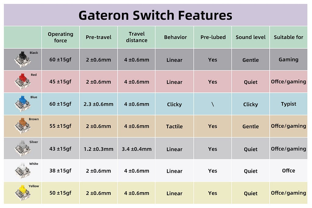
The switches, I ordered Milky Yellow Geatron, have two prongs below that fit into the Switch sockets we soldered onto the PCB on the other side. These should click into place without too much pressure. Depending on your case you may have a piece that will go on top of your PCB to hold it into the casing. Place 4 switches in each corner and then screw the hardware into the case, this makes it easier to have it all lined up.
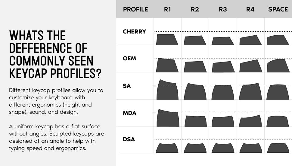
Keycaps:
Each keycap will fit snuggly onto the switches to complete the look of your assembled keyboard. You can have many different profiles of switches, I ordered DSA, giving the keys a more uniform look.
Hardships I Faced
At points, I did not think before soldering and it got me into some sticky situations. Spare parts can save you! I soldered the diodes in the reverse direction, which makes your board useless unless you fix it. I also soldered a microcontroller in place before tucking the battery under and giving myself no room and extra work to remove the soldered microcontroller and make space for the battery. I ordered hot-swap sockets after this incident so I did not need to go through this pain again.
The hardest part of this was desoldering the pins. The solution that worked best for me was to add flux to my solder wick and desolder each pin but that will not unsolder the pins completely. To desolder, I had to press the iron on the bottom point of the pin to heat it enough and provide pressure to push it up and out.
If you run into any LED issues, the previous or faulty LED could be the issue, because each one depends on the previous. I hope if you follow this guide and avoid my mistakes you get a nice experience with a great keyboard.
Testing It Out — Conclusion!
Your final product awaits, the only thing to do left is to get used to it by typing out a comment or the URL to my profile so that you can subscribe for more tutorials and content. I enjoyed the process of this build and cannot wait to explore what else I may be able to build with the leftover resources and tools!